Unwrapping UV Textures in Blender
What is a UV Texture?
Per the Wikipedia article on the subject:
UV mapping is the 3D modeling process of projecting a 3D model’s surface to a 2D image for texture mapping. The letters “U” and “V” denote the axes of the 2D texture because “X”, “Y”, and “Z” are already used to denote the axes of the 3D object in model space, while “W” (in addition to XYZ) is used in calculating quaternion rotations, a common operation in computer graphics.
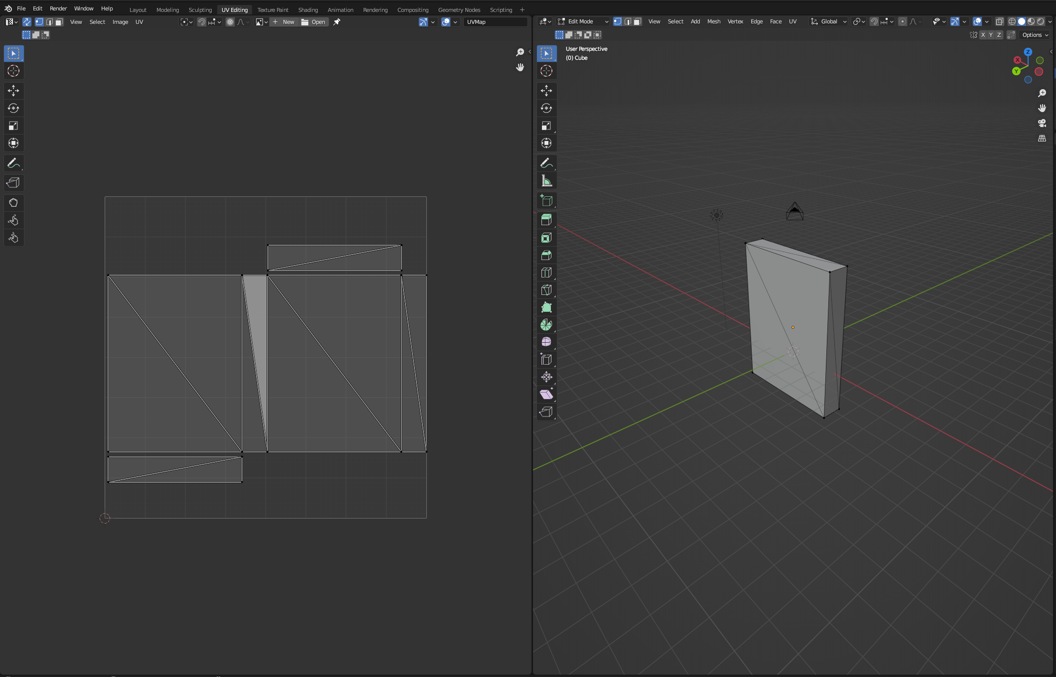
Blender has its own UV Editor tab, which we will be using for the purpose of the demonstration of UV Unwrapping:
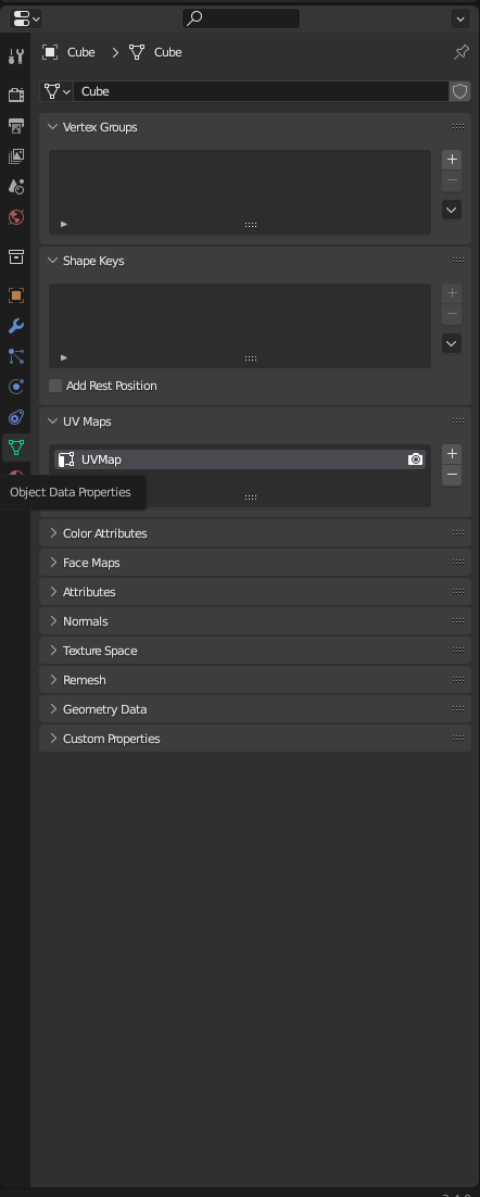
By default, in Blender, when a mesh is created, it comes with a UV map included, under the Object Data Properties tab on the right side:
For our purposes here, we’re going to be messing with this default UV map to see if we can get it to match up to the shape that we change the mesh to.
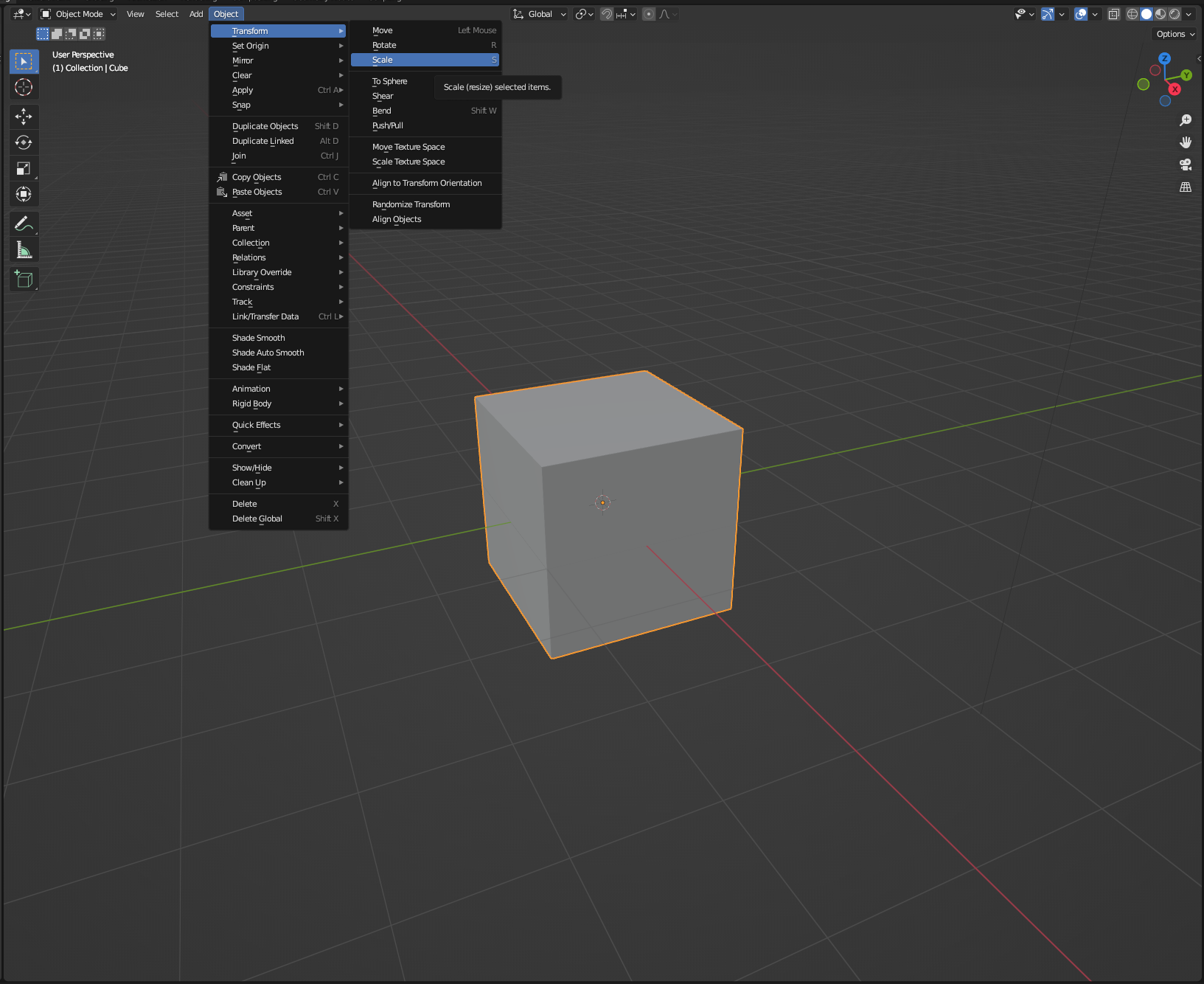
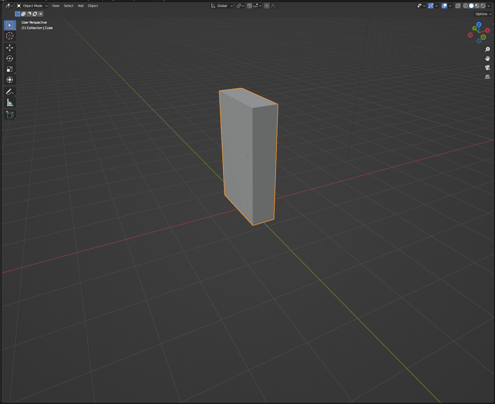
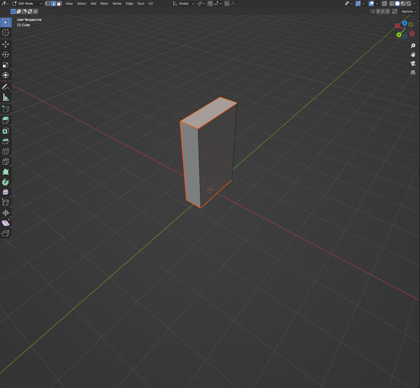
To start, let’s edit the scaling of the mesh’s sides to make a “cereal box” shape. In Blender, scaling is changed by using the S hotkey, or by navigating to the Scale tool in the Object > Transform > Scale submenus (if you want to go the long way ‘round).
You can also lock the axes of your actions by using the x,y, or z hotkeys, or by using the mouse to point at the axes themselves (identified by red, green, or blue lines, respectively) and pressing MIDDLE MOUSE BUTTON by default. More on axis-locking here.
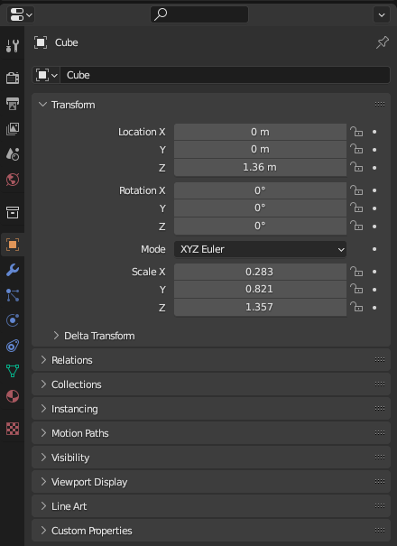
Once we’re finished making the box to our specifications, we have to apply our transformation to the mesh to set the values of all of our properties (location, scaling, etc.) to 1. This lets Blender know that this is the actual size of the mesh, and to change all other properties accordingly (including our UV map, which is pertinent to what we’re doing here). The preview of the Object Properties prior to applying the transformation:
Applying the transformation can be done by using the Ctrl+A hotkey, or by navigating to the Object > Apply submenu, and choosing the parameters that were changed during the original transformation.
With the transformations applied, let’s Tab into Edit Mode, and Select everything (the a hotkey). Once we’ve selected everything, we look at our UV editor window:
That’s weird, the UV map is still showing squares, rather than the rectangles of the cereal box! It turns out that we need to mark seams (think, the edges connecting the faces that comprise the mesh) and unwrap the UV map again.
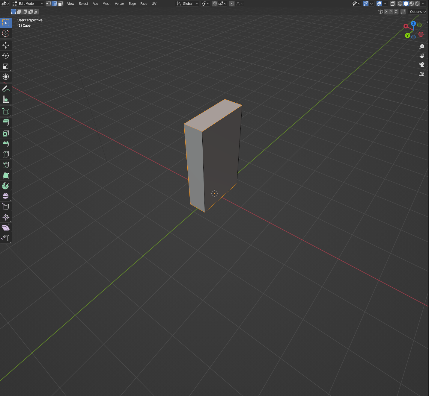
To mark seams, while in Edit Mode, go to the Edge select mode:
Select all the edges you would need to “unwrap” the mesh:
NOTE: If you’re using the UV map that came with the mesh, you may have to clear the previous seams before applying new seams. Alternatively, you can remove the UV map entirely in the Object Data Properties menu and create a new one.
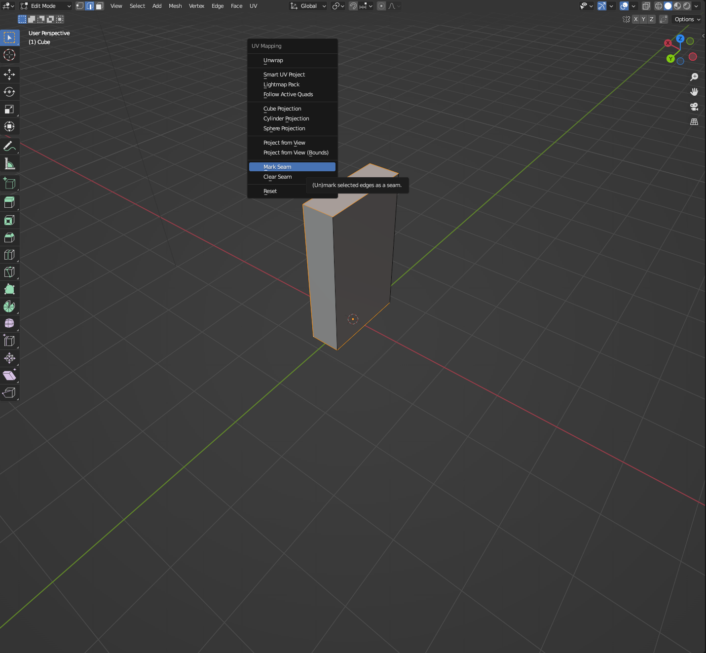
To use the Unwrap tool, simply press the u key, or navigate to the UV > Unwrap submenu. This should give you access to the Mark Seams and Clear Seams tools.
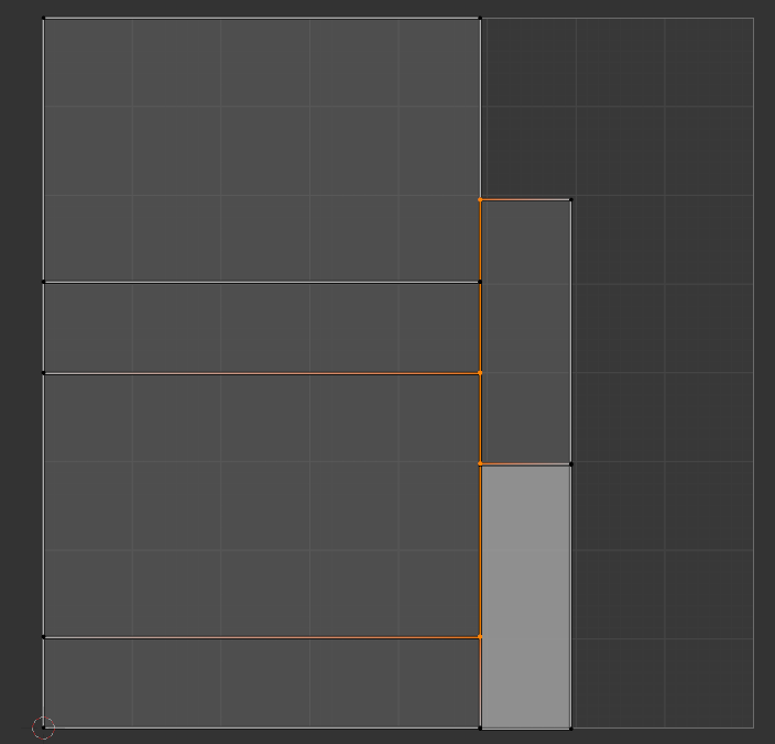
Once you mark seams, they should appear darker:
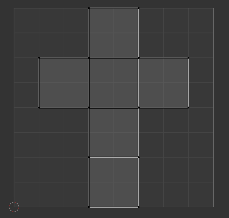
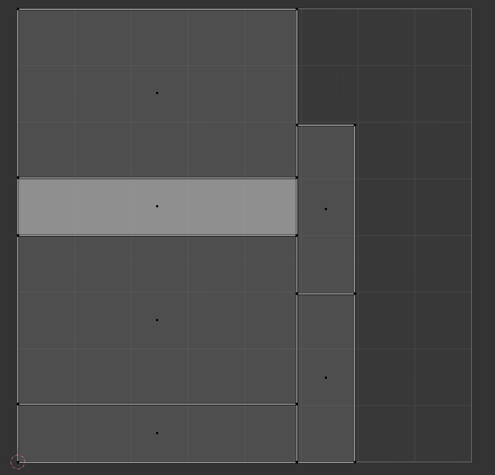
Now, using the Face Select mode, select all faces and Unwrap your mesh. Your new UV should appear in the UV Editor:
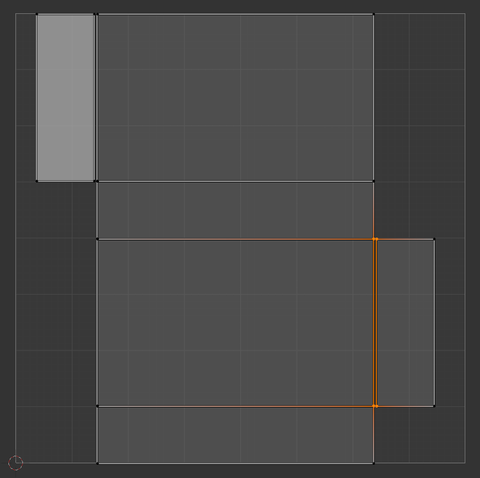
Excellent! Now, it’s important to check the edges of the islands (faces that are unconnected to the greater UV map, like the above top and bottom faces) to ensure that they match up to the correct areas. Make sure you have the UV Sync Selection option enabled on the UV Editor tab so that you can see where on your mesh the edges line up:
You can grab the individual faces and move them around by using the G hotkey, or use the Move tool along the left side. Move the faces to their approximate correct positions (this doesn’t have to be perfect).
For the sake of clarity, I’ve rotated the above UV Map 90 degrees to make it easier on myself when I begin to map my texture to the UV map.
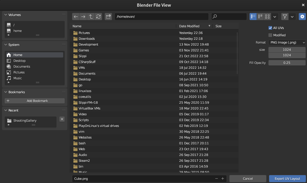
Now we can export this UV Map to a .png file using the UV > Export UV Layout submenu tool to make a template, complete with an transparent alpha channel:
I already know that the texture I’m going to be working with is a 1024x1024 texture, so I don’t have to change anything in this menu other than ensuring that the All UVs button is checked.
Hit the Export UV Layout.
We won’t be covering UV Texture Painting here, but that will be covered in another post later.
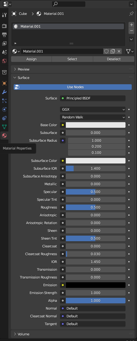
Once we have our texture arranged correctly according to the layout that we exported, it’s time to import the image as a texture using the Material Properties tab:
I personally prefer to get rid of the default material and create a new one, but it is also possible to edit the existing material.
Once the material exists, you can then go down to the Base Color option and hit the button next to the text.
You should be able to navigate to the Image Texture option. Once you’ve selected the option, the Base Color option should give you the ability to open a file. Select your texture.
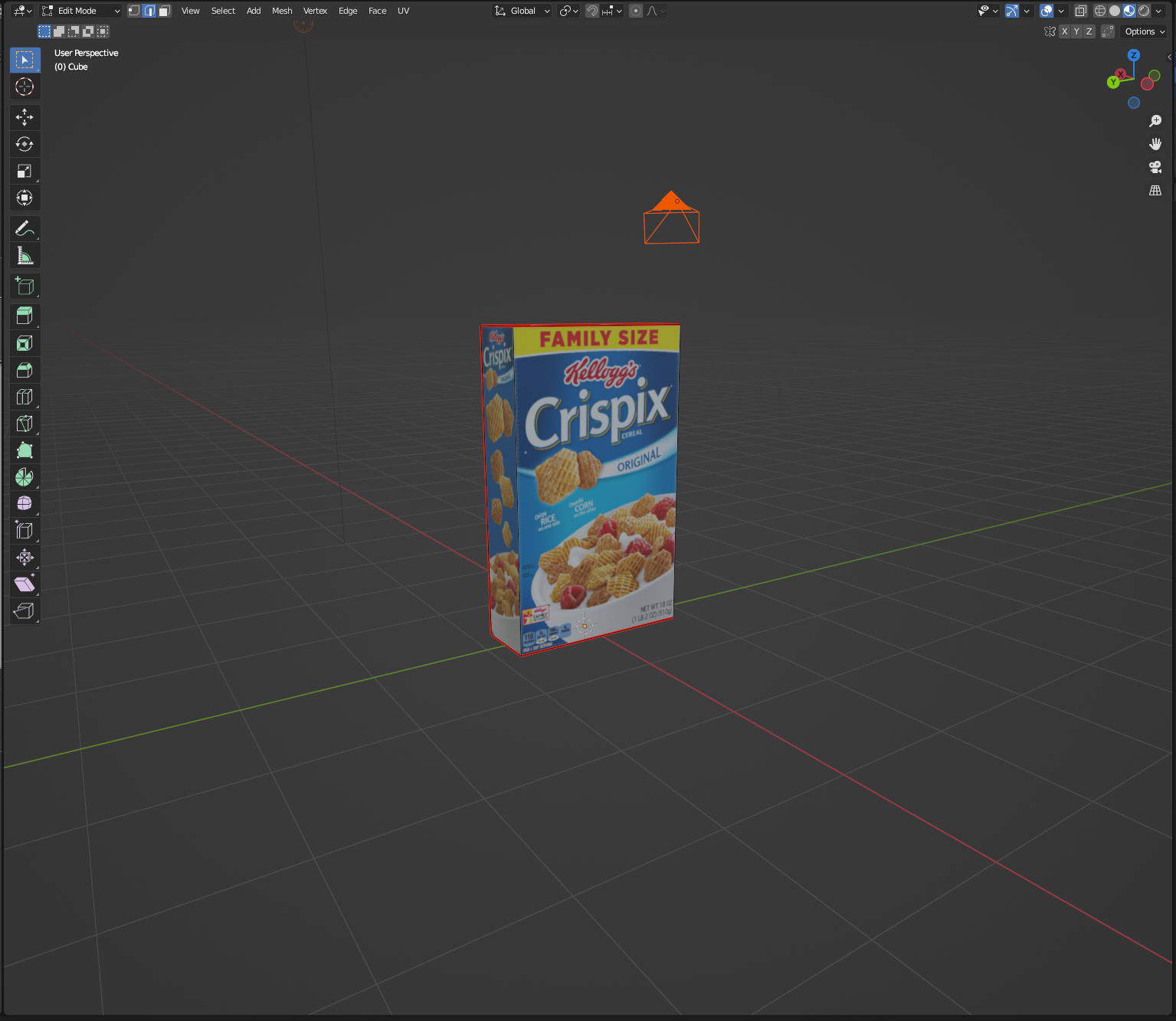
And there it is! The material has been successfully applied to the model.
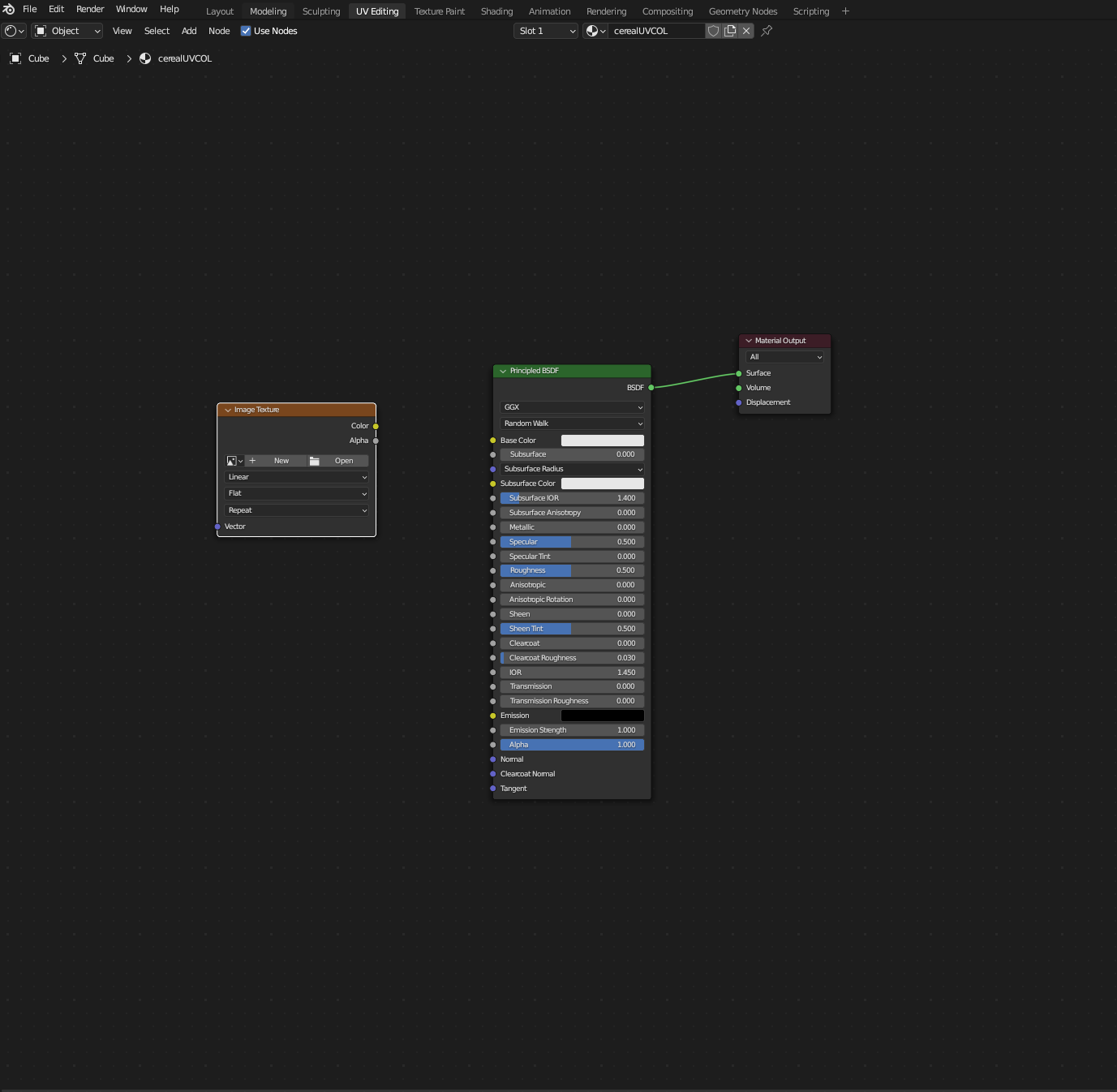
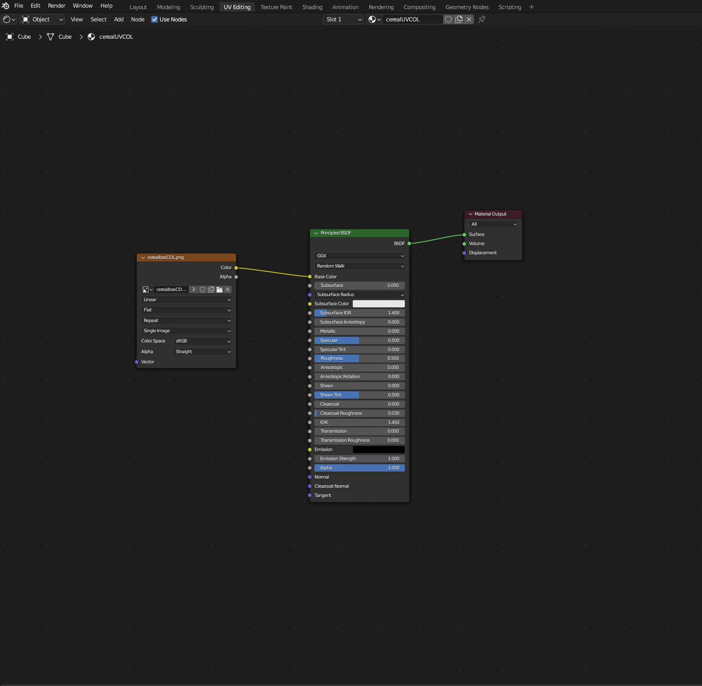
You can also accomplish this by using the Shader Editor, once you’ve created a new material. To import the image in the editor, just go to Add > Texture > Image Texture submenu, which should generate an Image Texture node:
Like what was done in the Material Properties tab, open your image in the node. Once finished, you should be able to “connect” the image’s Color output socket to the Base Color input socket:
And just like that, you’ve added an image to your mesh! Because you’ve assumedly arranged your texture to fit your UV map, the texture should fit perfectly.
NOTE: Please keep in mind that you can accidentally delete the Principled BSDF or the Material Output shader nodes that gets generated when you create a new material. Not to worry, you can repopulate them by navigating to the Add > Shader > Principled BSDF and Add > Output > Material Output submenus respectively.
